How it works
The science
What the instrument actually solves, why it looks like real metallography, and where the model's honesty ends.
01 The model
SOLIDIFY integrates the Kobayashi (1993) anisotropic phase-field model for an undercooled melt, extended to many grains and a dilute solute. Two coupled fields live on every cell of a 512²–2048² grid: an order parameter φ (0 = liquid, 1 = solid) and a temperature T, with a solute concentration c and a solidification-age channel alongside.
Everything the instrument shows follows from these lines. There is no scripted behavior in it: no drawn arms, no prebaked snowflakes, no particle effects. The landing page opens on a rendered model, and says so.
02 Why dendrites happen
A flat solidification front in an undercooled melt is unstable: any bump reaches into colder liquid, dumps its latent heat faster, and grows faster still — the Mullins–Sekerka instability. Latent heat (the K ∂φ/∂t term) makes each growing tip warm its own surroundings, so growth self-limits and selects a tip radius; the anisotropy ε(θ) breaks the symmetry so arms lock onto crystal axes. Four-fold anisotropy gives the classic metal dendrite; switch j to 6 and the same equations grow a snowflake, because ice is hexagonal. Interface noise seeds the side-branches, exactly as thermal noise does in reality.
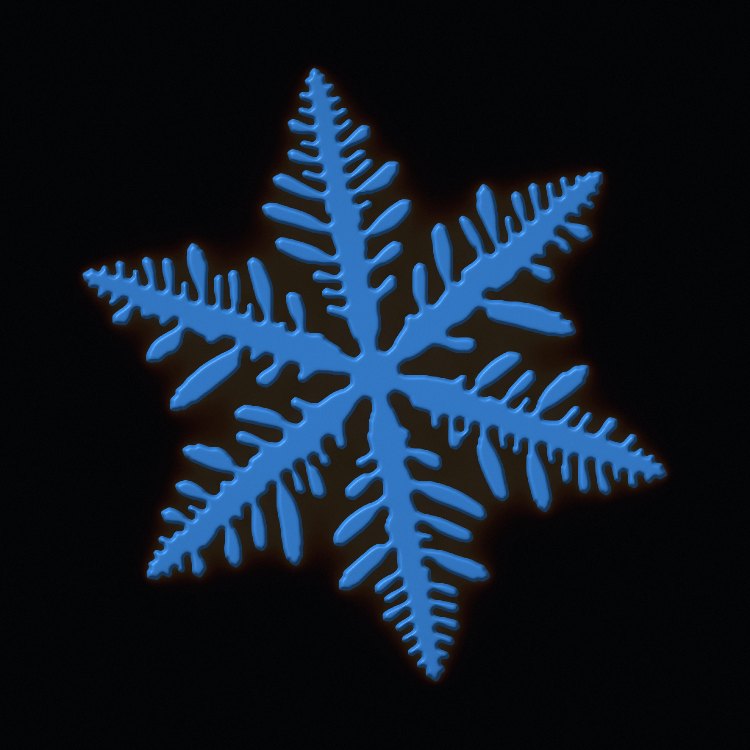
With the anisotropy turned nearly off the model grows seaweed (dense-branching morphology), and with a pulled thermal frame it reproduces columnar growth and the columnar-to-equiaxed transition — all canonical, all emergent.
03 Many grains and twins
Each nucleus carries its own crystallographic orientation θ₀ in a grain-ID field that propagates just ahead of the moving front: a newly solidifying cell adopts the identity of its most-solid neighbour. Where two fronts meet, growth stops and a grain boundary is frozen in — no extra model terms. The ASTM E112 grain number shown in the HUD is computed from per-grain pixel counts reduced on the GPU.
Twinning: with a set twin rate, a claim at the growth front occasionally spawns a new domain rotated by π/j — the maximal-misorientation 2D analog of a coherent twin. The twin must then out-grow its parent to survive, which is exactly the competition that selects feathery twinned grains in aluminum DC casting. Two 6-fold seeds locked at 30° grow the rare 12-branched snowflake. Twin boundaries etch faint in the micrograph lens, as coherent boundaries do under a real etchant.
04 The alloy chemistry
The solute field implements a Warren–Boettinger-type dilute alloy: the growing solid rejects solute (partition coefficient k < 1), which piles up ahead of the front and lowers the local melting point — constitutional undercooling, the engine of most real dendrites. The rejected solute freezes into the last liquid between the arms as microsegregation, which the XRAY lens renders the way synchrotron radiographs show it.
The alloy composer works in real chemistry. Each element carries approximate textbook dilute-limit binary coefficients (liquidus slope m in K/wt%, partition k). In the dilute limit these superpose:
Q is the industry-standard growth restriction factor (Easton & StJohn): it measures how strongly a composition slows crystal growth, and it predicts grain refinement. The composer collapses your mix onto the model's single pseudo-binary solute field so that ΔTL and Q are preserved (keff = 1 − Q/|ΔTL|, the m·c-weighted mean partition), and labels every clamp it has to make.
Before v4.0 this page reported a clean demonstration: under identical nucleation (a fixed 12 seeds/s rain) and cooling, grain-refined A356+TiB froze into 369 grains while nearly-pure Al–1Zn gave 46 coarse ones. Under the site model that comparison inverted — the lean alloy came out finer — and v4.0 withdrew the claim. v5.0 went back to it and found that the inversion was an artefact too. Two flaws, and neither is physics:
Equal bath temperature is not equal undercooling. A356's liquidus sits at 0.821 where the lean alloy's is 0.993, so at a common start temperature the refined charge began above its own liquidus and could not nucleate at all until it had cooled further. Equal time is not equal progress. Growth restriction left the refined charge with 25× less solid at the moment of comparison (fs 0.004 vs 0.106) — and grain count is counted on solid that exists.
Control both — start each charge at the same undercooling below its own liquidus, read both at the same solid fraction — and the honest answer is that the two alloys come out the same within noise. Across four independent runs at two inoculant charges one recorded set of grain counts read 1434/1380, 1431/1445, 305/313 and 351/327 — within 8 %, at the low end of a wider spread the paragraph after this one states in full. Growth restriction is unmistakably present — the refined charge takes about twice as long to reach 20 % solid — but at these site densities it does not translate into a finer grain count. Neither the original claim nor its inversion survives a controlled comparison.
How well "the same" is known, stated as the suite states it. The band the suite
actually asserts is 15 %, not the 8 % those four pairs happen to make
(REFINE-FAIR, on the two inoculant charges, at matched solid fraction). That
is the honest number, and the spread is not symmetric between the two arms. At 3000
sites the two charges track each other closely — seven recorded pairs (1434/1380,
1431/1445, 1433/1432, 1452/1461, 1409/1417, 1418/1420, 1449/1451) span 0.1 % to 3.9 %, and
the refined charge is the finer one in only two of the seven. At 600 sites neither
holds. Eight recorded pairs (305/313, 351/327, 356/340, 352/332, 363/337, 350/313,
376/319, 353/299) span 2.6 % to 18.1 %, the refined charge came out finer in seven of
the eight, and two of them — 376/319 and 353/299 — are gate failures at the 15 %
band. That is suggestive and it is not yet a result, because on
that arm the harness's own site-firing count is not a controlled variable: for the same
600-site charge the lean melt has been observed firing 349 sites in one run and all 600 in
another, which is the frame-pacing artefact the paragraph below this one describes. What
can be said is that the 8 % those four pairs make is the low tail of a wider population, and
that settling the 600-site arm needs the synchronous bench rather than the interactive
harness. This gate is also browser-only, so CI never runs it.
And the front door went on saying it for three releases. This page withdrew the
comparison in v4.0. The landing page kept animating a count to 369 grains against 46 and
captioning it as an eight-fold refinement by composition alone, "measured in this
instrument, not asserted" — which is the worst version of the mistake: a retracted number, presented as a
measurement, on the page most people read first. It was removed in v7.1 P6, and the reason
it survived a withdrawal, an inversion and a second withdrawal is that nothing checked it.
Numbers quoted as prose were being written by hand across six documents and recomputed by
nothing. PD-DOC-CONSTANTS now derives them — the table version, the Al–Si and
Fe–C invariants, A356's freezing range and four derive() outputs including the
two liquidus values in the paragraph above — from the modules that ship them, and bans the
retired claims by text in all six at once.
One further caution, recorded because it nearly became a third wrong answer. An
early v5.0 measurement appeared to show the textbook mechanism — the slower alloy
recalescing less, holding its undercooling, and firing every one of its 3000 sites
against the lean charge's 1640. It did not reproduce. The harness advances the solver
against wall-clock frames, and a GPU-backpressure guard skips frames unpredictably, so
the two casts had not received the same amount of physics. Site-firing counts from this
harness are not a controlled variable; grain count at matched solid fraction is,
which is why that is what the suite asserts (REFINE-FAIR). Settling the
mechanism needs a solver that can be stepped a fixed number of substeps regardless of
frame pacing — which the interactive harness cannot do, and which, as of v7.0, the
verification bench can: the controlled-experiment layer drives the nucleation model
synchronously between fence-paced substep chunks, so a cast with emergently fired sites
replays byte-identically per seed (EXP-REPRO-LIVE), and every sweep it
renders must name the variable it held fixed and prove the arms actually sat there
(EXP-SWEEP-CONTROLLED).
The composer's reported chemistry — ΔTL, Q, keff — is computed from the textbook coefficients throughout. Its conversion into the solver's units was itself wrong until v5.0: it used a flat 100 K per dimensionless degree for every metal, where the model's own factor is (L/cp)/K — about 249 K for aluminium.
The ANALYZE section adds foundry instruments: a cooling-curve probe (a thermal-analysis cup test — recalescence shows as the dip-and-rise), a Scheil overlay comparing the analytic Scheil path T(fs) = 1 − m·c₀(1−fs)k−1 against the measured interface temperature, and an SDAS ruler that measures secondary dendrite arm spacing by linear intercept, the same way a metallographer does it.
05 Numerics and the GPU
- Explicit Euler on a uniform grid, dimensionless units, dt held inside the stable envelope of the scheme; every UI slider range is clamped so instability is unreachable.
- Compact 9-point Laplacians. The naive divergence-of-central-differences builds an effective 2Δx Laplacian that decouples the two checkerboard sublattices and shreds the interface. SOLIDIFY uses the compact 9-point stencil plus a flux texture carrying the anisotropy terms (εε′φx, εε′φy, ε²), which keeps the front clean.
- All WGSL compute. Two passes per substep (flux, update) over ping-pong storage textures, roughly a billion cell-updates per second on a mid-range discrete GPU.
- Backpressure. One command submission per frame and a GPU-fence in-flight counter: slow devices throttle gracefully instead of freezing the tab.
- GPU statistics. Fraction solid, interface undercooling, per-grain areas (atomic counts → ASTM G), and the cooling-curve probe all come from a single reduction pass.
06 The third dimension
The TRUE 3D switch replaces the 2D grid with a full volumetric solver — up to 192³ ≈ 7.1 million voxels stepping the same Kobayashi equations in three dimensions. Surface-energy anisotropy becomes a function of the interface normal n̂ in each grain's own crystal frame (per-grain quaternions carry the orientation):
The volume is drawn by raymarching: a ray per pixel steps the φ field, refines the crossing by bisection, and shades the iso-surface with central-difference normals — nine lenses, from incandescent MELT to a volumetric NEON dark-field. The section plane (free depth, tilt and turn, CT sweep) is honest serial sectioning: the STEREOLOGY panel measures grain size on that plane and against the true 3D census, showing the classic section-plane underestimate that stereology exists to correct.
Shrinkage porosity is modelled by feed-path tracking: a flood fill from the riser (top face) marks liquid that can still be fed; liquid that solidifies while cut off becomes a pore, which x-rays dark in the FIELD lens exactly as casting radiography finds it. The flood honours the mould walls — a wall voxel is unconditionally excluded from the feed path every pass, so a chamber sealed behind a partition can never be reached by metal that never crossed it. At every freezing voxel the instrument also records the Niyama criterion Ny = |∇T|/√Ṫ — the foundry's standard porosity-risk index — and can paint it on the section plane. Numerics: explicit Euler at dt = 0.6·dx²/6 (the 3D stability bound — 0.53 is the 2D solver's margin against its own dx²/4), two compute passes per substep over ping-pong 3D storage textures, and 57 bytes of VRAM per voxel across nine textures — ~403 MB at 192³, with an out-of-memory ladder down through 160³, 128³ and 96³ (~50 MB) for smaller GPUs, every rung of it selectable from the ENGINE row.
The volume now carries the whole instrument. The dilute-alloy solute field runs in 3D (a lazily-allocated ping-pong texture pair — the composer's chemistry included), Bridgman growth pulls a thermal gradient up the z-axis, and a steerable laser welds the top surface with Beer–Lambert depth absorption. Growth twins nucleate at the moving front in true Σ3 registry — 60° about a parent ⟨111⟩, spawned on the GPU inside the grain-claiming pass — and the "forbidden" 5-fold symmetry gets its honest 3D answer: icosahedral interface energy built on the six 5-fold axes, growing twelve-lobed quasicrystal shapes. A cusped {100} energy grows genuinely faceted crystals. The one 3D-only scenario is the single-crystal grain selector: a helical "pigtail" channel mask under the Bridgman pull — dozens of chill-floor grains race in, exactly one orientation exits into the blade cavity, which is how real turbine-blade single crystals are actually made. The foundry instruments follow: the cooling-curve probe (ctrl-tap any voxel), the Scheil overlay, an SDAS ruler that measures λ₂ along any dragged line through the volume, and a stereographic [001] pole figure beside the symmetry-axis pole figure. The lab's mould is a rasterized geometry library — shell, plate, step, wedge — sharing one voxel-mask entry point regardless of shape. The step block is the classic foundry teaching casting: four section thicknesses fed from one common pour, each freezing at its own rate purely from wall-conduction geometry (no per-section parameter), and each measurable independently by the lab's own per-section census.
07 Nucleation, and the lab
Earlier versions of this instrument let you set the undercooling, the cooling rate and a nucleation rate in nuclei per second. That last slider was wrong, and a reader with a solidification background spotted it immediately: the nucleation rate is not something you set. It is a consequence of the other two. A melt nucleates when it is undercooled enough for the particles it happens to contain to become growth centres, and how deeply it undercools is decided by the competition between the heat you pull out and the latent heat the growing solid gives back.
So the rate is gone, and what remains is what a foundry actually controls — the inoculant. The charge carries nmax potential sites; each one has its own activation undercooling drawn from a Gaussian N(ΔTN, ΔTσ), and each fires exactly once, when the melt first gets that cold. This is the Gaussian site-distribution model that Thévoz, Desbiolles and Rappaz introduced for equiaxed casting and that CA-FE codes still use; the "fires once, when the melt first reaches its threshold" rule is the athermal picture Greer's free-growth model makes precise, where a particle's threshold is set by its diameter, ΔTfg = 4γ/(ΔSvd).
The consequence is the part worth watching. Sites only activate on a new maximum undercooling, so when recalescence sets in — latent heat warming the melt back up — the sweep stalls and nucleation shuts itself off, exactly as it does in a real casting. Cool the same charge faster and the melt reaches a deeper undercooling before recalescence catches it, so more of the same inoculant activates and the casting comes out finer. That coupling is not scripted anywhere in the code; it falls out, and the instrument's own test suite asserts it: identical charge, cooling rate 0.08 vs 0.45, roughly 300 vs 420 grains.
Lab mode exists because the rest of the instrument is a sandbox — you drag sliders and the melt answers. That is a good way to learn what each term does and a bad model of how the measurement is actually made. In the lab you fix the experiment first: the charge and its inoculant, the atmosphere, the pour superheat, the mould temperature and shape (3D — shell, plate, step or wedge), and a cooling programme (furnace, air, quench, or a soak-then-cool hold). Then you pour it and watch. The solver follows the programme's set-point with Newtonian shell coupling rather than a constant heat sink, which is what lets a hold really hold. At the end you get a report card: the cooling curve read the way a foundry reads a cast cup (TL, TN, recalescence, TS — the thermal-analysis row below says what that extraction can and cannot resolve), the deepest undercooling reached, how much of the inoculant survived the hold and fired, the dissolved-hydrogen ledger, and — since the lab judges as well as measures — the as-cast grain census with its Hall–Petch yield strength, held against a pre-pour spec if you dialled one. The spec is latched at the pour, so moving it after the metal is in the mould cannot rewrite the verdict; a miss points back at this panel, because a finer pour closes it (more inoculant, a shorter hold, a faster programme) where the furnace can only move it further away. Change a physics dial while it is pouring and the card says so — a run with the conditions moved under it is a demonstration, not a measurement. Pour the step block and the card gains a fifth reading: a per-section table, thickness against local d̄ against σy, thinnest first — the same census machinery run four times over four regions of the one casting, so the section-thickness effect is a measurement, not an illustration.
08 The calibrated solver
Everything above this point is a similarity model. It grows the right shapes for the right reasons, but its interface width and relaxation time are dials — you pick ε̄ and τ, a dendrite appears, and its tip radius is a shape rather than a prediction. The SCALE panel has always said so: the capillary ratio d0/W reads not defined, because there is no calibrated surface energy anywhere in the Kobayashi model to define it with.
The calibrated solver closes that hole. Karma and Rappel's thin-interface asymptotics relate the phase-field parameters to the two numbers a material actually has — the capillary length d0 = Γ/ΔT0 and the diffusivity D — through
so once λ is chosen, W0 and τ0 are forced, and with them the physical size of a cell and the physical length of a timestep. Seven dials stop being choices. For Al–4.5Cu that works out to d0 = 3.2 nm, W0 = 109 nm and a cell of 0.087 µm, so a 1024² grid is a 89 µm field of view — and the SDAS ruler starts reporting arm spacings a micrograph of the same alloy would give, rather than whatever a declared 1 mm domain happened to imply.
λ is the only knob left, and it is a convergence knob, not a physics one. It sets W0/d0: how many capillary lengths wide the diffuse interface is. The asymptotics are exact as that ratio goes to zero, so every quantitative claim has to be shown independent of it — which is a test, not a promise, and it is the test a pretty dendrite cannot pass by looking pretty.
In an alloy the model also carries an anti-trapping current. With no diffusion in the solid, an interface of finite width traps solute it should have rejected; the error is not small and not random, it looks exactly like a larger partition coefficient, and a dendrite grown with it is entirely convincing. The current cancels it. Measured here: with the current on the effective partition coefficient sits on the real k and does not care how wide the interface is; with it off, keff runs 24–40 % high and the excess grows with the width.
One consequence arrives for free. Under the calibrated alloy path one dimensionless degree is the alloy's freezing range rather than the latent-heat interval L/cp, and the app's own shipped nucleation potency — the same dial, unchanged — reads 11 K instead of 37 K. That is the band real castings occupy, reached by fixing the temperature scale rather than by touching the nucleation model.
Which alloy's freezing range, though. Until v7.1 it was the base material's: ΔT₀ came
from materials.ts's liquidus slope and partition coefficient, which for aluminium
are −3.4 K/wt% and 0.17 and are labelled, in that file, as Al–4Cu. Pour A356 through the
composer and the thermometer, the clock, the cell pitch and every SI readout downstream were
computed for a different alloy — for 4340 steel one dimensionless degree came out as
1504 K. The calibration now takes the poured mix's own numbers: the m·c-weighted mean
slope and the m·c-weighted mean partition, which are exactly the pseudo-binary the solver
integrates. 4340 reads 78 K, IN718 65 K against a published ~76 K, AZ91 121 K against ~130 K.
And where that stops being a freezing range, the app says so. ΔT₀ = |m|c∞(1−k)/k is not a thermal quantity dressed up — it is a composition scale. Written out, the capillary length is d₀ = Γ/[|m|(1−k)·cref], and it collapses to Γ/ΔT₀ for exactly one reference liquid: cref = c∞/k, the steady-state planar front. That is the reference this solver's supersaturation is built on. It is also, for any alloy past its primary phase's solubility limit, a composition the melt never reaches — A356's is 53 wt% Si against a 12.6 wt% eutectic. So past that point the composer keeps the model's own gauge, because it is what the kernel measures in, and labels it EXTRAPOLATED GAUGE: it names the reference liquid, the invariant that has been passed, and the alloy's real primary freezing range beside it. For A356 that reads 303 K of model interval against 35 K of real primary freezing — a factor of 8.7, printed rather than buried. A mix whose weighted partition falls outside (0,1) at all — A356 plus a titanium refiner reads −0.59, because a k = 9 peritectic solute and a k = 0.12 eutectic one do not average into a pseudo-binary — is declined, and the calibration keeps the material's own coefficients and says which clause fired.
And now it is drawn. The composer carries a phase diagram for the poured mix's
dominant binary — the solute with the largest |m·c| — built from the cited invariants in
phasedata.ts (table version 1.1.1, bumped on any row change, and every row
independently recomputed from openly-licensed CALPHAD assessments in
docs/PHASE-AUDIT.md
so a reader can check any one of them without taking this file's word for it) and drawn as
STRAIGHT CHORDS from the pure metal's melting point to the invariant. The straightness is the point rather than a compromise: those chords ARE the
linearised diagram this solver integrates, so the figure is a picture of the model and the
real curvature becomes a caveat the panel prints instead of a feature it silently lacks. The
pour marker sits at the MELT's own liquidus, not the binary's, and the gap between them is
drawn and labelled — for 4340 steel the four non-carbon solutes pull the melt 13.3 K below
the Fe–C liquidus, and that shift is in the solver and is not on the diagram. Where a model
clamp has moved the depression the solver actually integrates, a second dashed line goes to
that point with the clamp named beside it; 1045 steel prints 40.7 K of depression and
integrates 12.9 K. A dashed cursor tracks the melt's live temperature and is simply ABSENT
when there is none — off the diagram, past the solidus, or on a material with no
thermometer — rather than pinned to an edge at zero.
What the figure will not do. It is the dominant BINARY, never the alloy's own diagram: for IN718-lite that is Ni–Nb, and the Laves phase and Nb-rich interdendritic liquid that make IN718 interesting are on neither the drawing nor in the solver. The panel says so on every multi-solute mix, with the dominant solute's share of the depression computed rather than quoted. And one shipped row is refused outright: Ni–W's invariant at 1495 °C sits above nickel's 1455 °C melting point, which means the liquidus rises and the first solid must be the richer phase — but the row's C_SM 39.9 wt% against C_inv 45 wt% says the liquid is. Drawn, its solidus would cross above its liquidus. Which of the three numbers is wrong has not been resolved here, so nothing is invented: the row keeps the numbers as read from the ASM figure, records the contradiction in its own source, and the figure declines to draw it.
Which phases, and which of them are actually grown. A diagram is only worth drawing
if it answers the question a founder asks first: at THIS composition, what does equilibrium
leave when the casting is frozen? The composer answers it in two columns, and the milestone is
the gap between them. EQUILIBRIUM LEAVES is read off the cited invariants; SOLVER GROWS is
always exactly one, the base-rich primary, because sim.ts
and sim3d.ts carry one φ field and one solid phase. A356 at 7 wt% Si is past the
1.65 wt% that dissolves in (Al), so equilibrium ends it as (Al) + (Si) and the lever rule puts
49 % of the casting through the 577 °C eutectic — Gulliver–Scheil, which assumes a constant
partition and no back-diffusion into the solid, says 51 %. This solver grows none of it. Both
closed forms use the row's own chord partition k = CSM/Cinv rather than
the shipped dilute k, and both numbers are printed. For a PERITECTIC the phase is named and
the number is refused — and the reason is a property of the quantity, not of the
tools. At a eutectic every drop of liquid remaining at Tinv freezes there, so the
liquid fraction IS the share that freezes at the invariant. At a peritectic the reaction
consumes only part of that liquid and the rest freezes BELOW Tp on the product's
own solidus, which makes the share a difference of two lever arms this table cannot close.
(An earlier draft of this paragraph said the lever rule and Gulliver–Scheil "do not describe
a peritectic". That is false on both halves — the lever rule is a tie-line mass balance that
knows nothing about reaction type, and Scheil is the standard tool for hypo- and
hyper-peritectic steel — and by this project's own rule a refusal that names the wrong
mechanism is a wrong statement rather than an absent one.) What the app does print for
a peritectic is sharper than a fraction. 1045 steel's 0.45 wt% C is past the 0.09 wt% that
dissolves in δ-ferrite, so a second phase is coming; and it is also past 0.17 wt%, the
composition of the reaction's own product, so L + δ → γ consumes the δ-ferrite entirely
and the casting ends as austenite alone — while this solver grows δ-ferrite from the first frame to the last.
Its two columns read gamma-austenite against (Fe). A melt leaner
than that product keeps some δ and the readout says so instead; Fe–Ni's product composition
is a bracket in the literature rather than a number, so that row declines to decide. The
regimes are deliberately not called hypoeutectic: seven of the shipped rows are
peritectics and the word would be false for all of them. One honest consequence, printed
rather than hidden: the maximum solid solubility in this table is quoted AT the invariant
temperature and there is no solvus below it, so whatever precipitates on further cooling is
outside both the drawing and the solver.
And equilibrium is not the only thing with an opinion below the solubility limit.
A melt leaner than CSM freezes single-phase only if the solid keeps up by
diffusion. Gulliver–Scheil assumes it does not, and it is defined on that side of the
boundary too — with no back-diffusion the last liquid between the arms still enriches to the
invariant, however lean the melt started. So the readout prints both: AZ91 at 9 wt% Al is
inside Mg–Al's 12.9 wt% equilibrium limit, and Scheil puts 11.9 % of that casting through the
437 °C eutectic as β-Mg17Al12 — which is the textbook as-cast
constituent of AZ91, and which this solver grows no more than it grows the equilibrium one.
AA2024's copper gives 8.8 % and the galvanising bath's aluminium 1.5 %. Below 1 % of the
casting the app stops calling it a phase, and that floor is not roundness: the two tables
this app ships disagree about k by ratios from 0.39 to 3.30 across all twenty-three rows with
an invariant, and from 0.68 to 2.34 over the fifteen PD-CONSTRUCT-AGREE actually
enters, so a predicted fraction of a few thousandths is smaller than the coefficients can
support. Leaving this out would have been
the one place the two-column device failed to fire — on a dendritic-solidification simulator,
where non-equilibrium freezing is the entire subject.
And the composition ceiling now comes from the diagram. Each solute used to carry a
hand-picked slider maximum doing two jobs at once — an ergonomic, and the only thing standing
between a user and a melt whose first phase this solver cannot grow. It keeps the first job.
The second is derived: past the invariant liquid the FIRST solid to appear is no longer the
base-rich one, so that composition is refused inside derive(), where a hand-built
#alloy= link and window.__solidify.alloy cannot walk around it, with
the phase and the number named. Measured against the table, the hand-picked cap reached past
the invariant for five of the twenty-five pairs — and one of them, Zn–Al, had its slider
maximum sitting exactly ON the eutectic at 5 wt%. Cast iron therefore leaves the
composer. Fe–C stops at 0.52 wt% C against the 0.53 wt% peritectic: past it the primary
phase is austenite, and this app models the steel as bcc δ-ferrite, so what it drew for a
3 wt% C melt was not an approximation of cast iron but a different casting altogether. 1045
and 4340 are unaffected at 0.45 and 0.40 wt% C. Existing deep links are never rejected for
this — they restore, clamp to the ceiling, and say so on the same channel the clamps and
refusals already use.
And the input chemistry now opens onto the whole periodic table, while the output to the solver stays a one-channel pseudo-binary. A table of all 118 elements carries six numbers each — atomic mass, a radius, a Pauling electronegativity, a melting point, a boiling point and an enthalpy of vaporisation. Four of them are read by a refusal and two are recorded and not: the electronegativity difference is the OTHER Hume-Rothery rule, the electrochemical factor, which this file deliberately does not apply, and the vapour rule takes its temperature from the BASE rather than from the element. Every one of the 6 × 118 = 708 (base, element) pairs is placed in exactly one of four tiers with a sentence saying why. Exactly 25 are ASSESSED, which is precisely the set that already had both a cited coefficient row and a cited invariant row: this adds no new pourable chemistry at all, and that is the point. The other 683 are the content. 47 elements are refused before the base is even consulted — the noble gases (a closed shell and no metallic bond), the halogens (an ionic salt or a volatile halide, which is the flux that covers a melt rather than anything dissolved in it), the 35 elements that are not primordial, and H, N and O, whose content is set by the atmosphere over the melt rather than by a weight you add. That last tier is base-INDEPENDENT while its physics is not, and the refusals say so per base rather than quoting one law six times: hydrogen obeys Sieverts' law C = S·√p in every one of them and is already modelled in aluminium, where the porosity layer carries real solubilities; nitrogen obeys it in iron and nickel, does not dissolve in aluminium or magnesium but REACTS to AlN and Mg₃N₂, and is near-insoluble in copper, which is why it serves there as a purge gas; and oxygen dissolves in iron and is measured in-ladle with a probe, reports to dross in aluminium, and in copper is a deliberate compositional variable — tough-pitch copper carries 0.02–0.05 wt% of it on purpose, which is the one cell in this grid where a user would be right to expect a number. Sulphur and phosphorus are deliberately NOT in that gas tier. They are dissolved solutes obeying dilute-solution thermodynamics, and they are the canonical low-k segregators — the physics this solver models best; pointing a user at the hydrogen porosity layer for sulphur would point them at a layer that models hydrogen and nothing else. They are refused for the honest reason instead — no coefficient row has been entered — and entering Fe–S and Fe–P is named as the single best addition this table could take.
The vapour rule is where two tabulated numbers reproduce foundry practice, and it advises rather than refuses. Clausius–Clapeyron anchored at the boiling point times Raoult's law, pi = xi·exp(−ΔHvap/R·(1/T − 1/Tb)), evaluated at the base's own melting point: zinc reads 59 atm over liquid iron, which is why zinc-coated scrap fumes off as ZnO in a steel charge — a yield loss, a fume hazard and a baghouse-dust problem rather than a prohibition, since coated scrap is normal EAF feedstock and a zinc-recovery industry exists downstream of it; magnesium 16 atm, which is why nodularising ductile iron is a plunge and not a stir; mercury 39 atm over liquid aluminium; and manganese 0.037 atm, which is a welding-fume hazard and correctly not a reason to refuse manganese steel. Applied as a refusal the same rule refuses brass — Cu–30Zn computes 1.4 atm and brass is real, because zinc's activity in copper is far below ideal and the activity coefficient that would fix the number is exactly what this app does not carry. So every line above the fume threshold says that out loud. Two more honest limits are printed rather than hidden. The rule is evaluated at the pure base's melting point, because only 16 of the 118 elements carry a coefficient row in any base at all and the rest have no liquidus to depress; recomputing every assessed pair at its own depressed liquidus moves the answer by 3 % for the only assessed pair whose pressure even reaches the fume band (Cu-Zn); for the rest it lands on numbers so small that nothing about them is a decision. And the size rule knows which convention it is subtracting: Hume-Rothery's 15 % band is about substitutional solubility, and applied to Fe–C it returns a meaningless −39.6 % because it is differencing carbon's covalent radius against iron's metallic one for an atom that never occupies a substitutional site. Carbon, nitrogen, boron and hydrogen — four elements, not three — are screened by Hägg's r/R < 0.59 interstitial criterion instead — where Fe–C's 0.604 sits just outside the limit, which is why Fe3C is a complex orthorhombic carbide rather than a simple interstitial phase.
The limit this milestone makes easier to violate, stated plainly. The composer sums solutes in the dilute limit: ΔTL = Σmici and Q = Σmici(ki−1), which assumes zero solute–solute interaction — every addition behaves as though the others were not there. That is a fair approximation for the dilute, few-element presets this app ships and it is not one for an arbitrary handful of elements off an open table, which is exactly what an open table invites. The mix then collapses onto ONE pseudo-binary for the solver, because there is one solute field: the m·c-weighted mean partition, with the largest |m·c| term naming the binary the figure draws. Nothing about opening the input widens that channel. Two more things this table will not do: it ships no ESTIMATED tier and no Darken–Gurry ellipse (measured once over this app's own 25 pairs, that ellipse rejects 10 of them and eight of the 9 presets contain at least one pair it rejects — the galvanising bath, whose only addition is Zn–Al, is the single exception — a category error, since it predicts extensive solubility while every casting solute here is dilute and bounded by an invariant. The ellipse is deliberately not in the code, so nothing in the build re-derives that count), and it does not infer miscibility gaps from Miedema's ΔHmix, whose sign gives neither a gap temperature nor a gap composition. Five monotectic systems have been checked and are refused by name — cu-Pb, al-Bi, al-In, al-Pb, fe-Ag — and an unlisted one is refused for being unchecked, never for a mechanism nobody looked up.
v7.1 P5 puts that table on screen, and the refusals are the part you can see. The composer's "+ add element" list is closed — six solutes at most for any base, every other element simply absent — so it answered "what does mercury do to an aluminium melt?" by not listing mercury. Beneath it now sits the periodic table, all 118 elements laid out in 18 columns, coloured by tier for the melt you are standing over, and every cell answers when it is tapped. Each is classified at 1 wt%, or at half its own invariant composition where that is smaller, and the qualifier is not fussiness: at a flat 1 wt% three of the twenty-five pourable pairs — al-Ti, fe-C and mg-Zr — classify as OUTSIDE-THE-MODEL, because 1 wt% is past all three of their invariants, so carbon-in-steel would have painted as a refusal the moment the panel opened. Switching the base from aluminium to iron moves 14 of the 118 cells into a different tier and leaves 104 where they were; a second channel moves independently of the first, as a fume stripe appears under 10 more elements whose tier does not change at all — sodium, potassium, calcium and cadmium among them — because the rule is evaluated at the pure base's melting point, and every one of their boiling points falls between aluminium's 660 °C and iron's 1538 °C. Not by much, at either end: caesium boils 11 K above the aluminium melting point and calcium 54 K below the iron one, so "hundreds of degrees" — which is what this paragraph said first — is wrong in both directions. The one-line reason a cell carries is composed in the classifier and never cut from the paragraph: every one of these sentences puts its number in the middle, so a truncation to fit a panel keeps the throat-clearing and drops the measurement. And opening the input changed no chemistry — all 9 presets and all 25 legacy pairs derive a bit-identical parameter bundle and an identical clamp list against a reference measured on the commit before this one, compared byte for byte rather than reasoned about.
What it is checked against, and what it measured:
| TEST | AGAINST | RESULT |
|---|---|---|
| Equilibrium interface profile | tanh of half-width √2·W0 | 0.997 W0 |
| Critical nucleus radius | Gibbs–Thomson R* = d0/Δ | 22.21 vs 22.10 W0 (0.5 %) |
| Steady tip velocity V·d0/D | Karma–Rappel 1998, 2D microscopic solvability at Δ = 0.55, ε₄ = 0.05: 0.0170 | 0.01679 (1.2 %) |
| Independence of interface width | same answer at W0/d0 = 1.8 → 3.6 | 6.4 % spread |
| Parabolic tip radius ρ/d0 | Tong, Beckermann, Karma & Li 2001: 27.6 | 28.8 (4.4 %) |
| Effective partition coefficient | the real k, independent of interface width | keff = 0.135–0.150 against k = 0.15; 0.186–0.209 with the current off |
| Solute conservation | flat over 20 000 substeps of growth | 1.6×10⁻³ |
And what it does not fix. The Lewis mismatch is unchanged — one explicit grid at one timestep still cannot carry heat and solute four orders apart, and the alloy path anchors on solute. The calibrated solver is 2D only; the volume still runs the Kobayashi model, and the switch says so rather than appearing and doing nothing. And the thin-interface expansion has a validity bound of its own, τ0V/W0 ≲ 0.2, which a deeply undercooled pure melt reaches by λ ≈ 4 — the app reports λ and the ratio it implies so that stays visible.
09 Heat treatment: the second clock
Everything above runs on the solidification clock, and under the calibrated solver a timestep on that clock is of order 10⁻⁷ s. A heat treatment is four hours — about 10¹¹ timesteps — so the phase-field solver can never be integrated through one: not slowly, not on a bigger GPU, not ever. Pretending otherwise would be the category of claim this page exists to rule out. So heat treatment is a separate model on a separate clock. You set a real schedule in °C and hours; every rate law the material shipped with is integrated over that schedule's whole trajectory — Simpson through the ramps, because an Arrhenius rate varies by orders of magnitude across one and charging only the hold under-counts a slow furnace by a measured 31 % — and the integrals become budgets a GPU pass then spends. φ is frozen for the duration, which is what solid state means, so the two clocks never have to be reconciled. No panel ever prints an unlabelled time: sim time is solidification, real hours are the furnace.
There is no process switch. You set an environment — a temperature schedule — and the model reports what happened: grains coarsened this much, solute flattened that much, this thickness of scale grew. "Stress relief" is not a mode; it is what you get when you pick a low temperature and every integral comes back negligible, and the report card says so because the arithmetic said so. This is the same move that deleted the nucleation-rate slider in v4.0: the dependent quantity stops being a dial.
Grain growth is a sublattice Monte Carlo Potts pass on the as-cast grain field, and its two
constants are measured, not assumed. Ideal curvature-driven growth is parabolic;
a Potts lattice is not — it pins, and its measured exponent comes out m = 2.44 in the plane
(three independent casts: 2.38 / 2.44 / 2.61, and this coincides with the canonical
Potts result R ∝ t0.41, measured here rather than adopted) and m = 2.25 in the
volume, where all the ingredients differ: 26 neighbours, eight sublattice colours, a cubic
lattice with its own pinning geometry. Assuming the textbook m = 2 costs a 4.8× error in
the sweep budget — in a number nothing else in the app would have contradicted — which is why
the suite makes the two exponents disagree on purpose (HT-SWEEPS) and re-measures
KMC's drift on every run.
Annealing twins appear in the volume, where a Σ3 — 60° about ⟨111⟩ — means something. The data decides who twins: stacking-fault energies were looked up with sources, and the matrix they produce is the teaching point. Copper (78 mJ/m²) and cobalt (≈20) twin; aluminium (166) and nickel (128) refuse with their numbers printed; steel refuses structurally, because it is modelled as BCC δ-ferrite and annealing twins are an austenite phenomenon this solver has no phase for. A twin that forms must also survive its own anneal, and that takes two pieces of real physics: a Σ3 energy cusp at the measured copper ratio (coherent ≈ 24 against general ≈ 625 mJ/m²) and a Σ3 mobility gate — coherent interfaces cannot migrate by single-atom shuffles, which is why twins survive where ordinary boundaries sweep past.
The plan's twin-spawn mechanism — a per-cell flip at the migrating boundary, the same idiom the growth twins use — was built exactly as designed and measured dead: 3 of 512 spawned twins survived 300 sweeps, and none survived 450. Adding the mobility gate (true physics) helped by 5× and was still dead. The real killer was geometric: a cell adopting a one-voxel twin pays ~12 neighbours of Σ3 energy where adopting its parent pays ~one — an artificial nucleation barrier no cusp value removes, because a {111} stacking event is sub-grid for a per-cell flip. Real annealing twins are born as plates, and mesoscale models in the literature insert them. So nucleation here is a stamped {111} plate in exact Σ3 registry on a probed boundary, and everything after birth is the pass's own physics. The plate is the one inserted thing — stated here for the same reason the 2D solver does not claim to resolve capillary-length nucleation.
Homogenization is its own pass — masked isotropic diffusion of solute through the solid skeleton at frozen φ — because under the calibrated alloy model the solid diffusivity is exactly zero and there is nothing to reuse. The map from schedule to iterations is exact: iterations = Dt/(cell²·D̃), with Dt the schedule's own Arrhenius integral — no wavelength, no fitted constant — which is why its gate can be an equality test: a seeded eigenmode of the discrete stencil must decay as (1 − 2D̃(1 − cos k))I, and does, to a relative error of 9·10⁻⁷ in both dimensions with conservation to 10⁻⁷. The continuum answer e−Dk²t differs from the discrete one by +0.012 % / −0.034 % at the tested modes, and that gap is printed, because it is the model's own discretization error. The cost wall is budgeted honestly: explicit diffusion under the calibrated 0.087 µm cell can demand millions of iterations, so the pass runs what fits and the card reports the delivered fraction of the requested Dt — never silently fewer.
Oxidation and decarburization are analytic card lines, not fields: scale grows as x = √(∫kp·dt) for every material with a sourced parabolic constant, and steel alone decarburizes as x = 2√(DCt), because steel is the one material here whose solute is carbon. The span is the teaching point — aluminium's passive film comes out 2.3 nm after 14.5 h at 520 °C ("aluminium does not scale", made visible) against steel's mill-scale millimetres. Ice and succinonitrile refuse by name: a zero in the constants table means "no constant was looked up", not "0 µm of scale". The scale is deliberately not painted into the fields — T, c and age are the as-cast record, and the card is where the number lives.
Strength rides the grain size. The report card closes with σy = σ₀ + kHP/√d̄ — Hall–Petch on the measured census, before and after — and a verdict against a spec you commit before the run, the way a real heat treatment answers to a drawing requirement. Three limits are printed with the number. It is grain-size strengthening alone: no precipitate term and no work-hardening term — a cold-work dial deposits stored energy here, but as a drive on the anneal and never as strength, so a deformed casting's σy still prices grain size alone; see the cold-work paragraphs below and the aging row. The d̄ under the root is the census's equivalent diameter (area-equivalent circle in the plane, volume-equivalent sphere in the volume), an O(1) stereological factor from the mean linear intercept the tabulated constants were fitted to. And the µm inside √d̄ stand on the declared resolution — "you set it" is the length anchor's provenance, and the strength inherits it. One consequence is stated rather than hidden: this furnace can only coarsen, and coarser is softer, so a spec above the casting's current strength is unreachable by any schedule. Meeting it takes a finer pour, and the panel says so before you waste the furnace time.
Cold work is the anneal's second driving force, and until v7.0 curvature was the only one. The volume's furnace carries a per-grain stored energy H — one f32 per grain id, 4096 of them, 16 KB in a storage buffer the GPU binds read and never writes — and the Potts acceptance line grows one term: dE = enew − enow + (H(cand) − H(mine)). A voxel that adopts a neighbour's grain id adopts that grain's stored energy with it, so the move costs their difference, which is negative when the candidate is the less deformed grain — the boundary sweeps into the more deformed grain and the less deformed one grows. That is strain-induced boundary migration, and it is the whole drive. There is no per-voxel field, and what removes it is an identity, not an approximation: h(x) ≡ H(id(x)) holds after every flip because it held before it, a flip being nothing but the adoption of a neighbour's id. The per-voxel version would have been 28.3 MB at 192³, 56.6 MB for the ping-pong pair; the per-grain buffer deletes the ping-pong, the lockstep, the parity argument and the out-of-memory refusal path along with the texture. The unit is the bond energy Jb, the Potts model's own, and stays that way: there is no SI-to-Potts energy bridge in this app and C3a does not add one, because the material law sets the endpoint and the measured lattice constants spend the sweeps, so no energy has to cross between the two.
The barrier that drive has to clear is derived, not fitted. A voxel on a flat {100} boundary sees 26 neighbours: 9 across the interface, 17 on its own side. Adopting the neighbouring grain swaps those counts, so a flat-front advance runs enow = 9 to enew = 17 — dE = +8 Jb, enumerated from the 26 offsets and owing nothing to the shader. At the shipped kT = 0.6 that costs exp(−8/0.6) ≈ 1.62×10⁻⁶ per attempt, so a flat front here is very nearly immobile and coarsening proceeds at kinks and curvature instead. It is the SCALE a stored-energy drive has to be read against — and it is an upper bound on the barrier that actually gates migration, not a measurement of it.
Measured on a bicrystal at 128³ over a 5-sweep window, deterministic to four figures across repeats:
| ΔH (Jb) | 0 | 1 | 2 | 3 | 4 | 5 | 6 | 7 | 8 | 9 | 10 | 13 | 20 |
|---|---|---|---|---|---|---|---|---|---|---|---|---|---|
| v (cells/sweep) | 0 | 0 | 0 | 0 | 0.0003 | 0.0142 | 0.1524 | 0.2173 | 0.3170 | 0.3380 | 0.3614 | 0.4330 | 0.5827 |
Three things that ladder says, each of which a "threshold at 8" story gets wrong in a different direction. The onset sits near 5–6, not 8. The exponential regime ends there: 4 → 5 is ×47 and 5 → 6 is ×11, but 6 → 7 is only ×1.4, where a pure Boltzmann tail at kT = 0.6 would keep multiplying by exp(1/0.6) ≈ 5.3 the whole way to 8. A front that has begun to move is no longer flat, and a kink carries a lower barrier than the flat face. The zeros are small numbers, not exact ones — a sub-barrier move costs exp(−(8 − ΔH)/kT), so over the gate's window on 128² boundary cells the expected count is a fraction of a flip at ΔH = 0 and about one at ΔH = 2; runs on identical code have read both 0 and 2, and the gate asserts the separation, creep three orders below the neutral-point rate, never v = 0. And the neutral-point velocity brackets 9/26 rather than confirming it. At ΔH = 8 the flat move is energy-neutral and this kernel takes neutral moves unconditionally, so a perfectly flat front would run at its candidate draw, 9 unlike neighbours of 26 = 0.3462 cells/sweep. The measurement runs above that in the first sweep and below it after — 0.3918, 0.3170 and 0.2137 at 1, 5 and 60 sweeps — and neither departure is noise. Above, because a sweep is eight sequential sublattice passes: the front roughens inside its own first sweep and the later colours see a raised unlike-neighbour count. Below, because recovery is live throughout, so a nominal ΔH = 8 has decayed to an effective 5.4 by sweep 60. There is no recovery-free arm to measure against — recovery is intrinsic to the stored mode — and an earlier version of this page quoted a "static" ladder that was not one.
What has teeth instead is that the ladder brackets the barrier from both sides, and the gate asserts both. A barrier of 10 would leave ΔH = 8 uphill by 2 and put v(8) near 0.3462·exp(−2/0.6) ≈ 0.012, thirty times under what is measured. A barrier of 6 would make ΔH = 6 the neutral point and put v(6) near the full draw, seven times over the measured 0.152.
Recovery has no pass. Dislocations annihilate second order, dH/dS = −k·H², which integrates exactly to HS = H₀/(1 + rec·H₀) with rec = 10⁻³·S — the 10⁻³ chosen so the stall lands mid-budget and then measured, see below — and the shader evaluates that closed form from one scalar the uniform already carried. Nothing is stepped, so there is no per-step ODE error and no f32 chain accumulated over thousands of sweeps, and recovery cannot be applied twice, applied per-colour instead of per-sweep, or land one sweep stale — it is never applied at all. Three properties follow with no clamp anywhere: HS ≥ 0, HS ≤ H₀, and HS strictly decreasing in S. High-H grains recover faster, so the spread of the drive narrows rather than merely rescaling. Driven from ΔH₀ = 20 on the same bicrystal, the front runs 0.3996 cells/sweep over the first 100 sweeps and is under a thousandth of that by 800, at HS = 1.18 — inside the band the ladder above measures immobile, and well inside the 2000-sweep cap, so a schedule the panel will accept can reach the stall. Every run so far has read a net displacement of exactly zero voxels in that last window, but the gate asserts the separation and not the zero, for the same Poisson reason the ladder's zeros are not asserted either. What makes it a measurement and not a restatement of the integral is where the stall lands: the ladder gate hands over the largest drive its own rungs measured below the creep floor, in the same run on the same GPU, and the recovery gate requires the front to start above that band and stop inside it. Recovery applied per-colour, applied twice or sign-flipped moves where the stall lands while still decaying monotonically.
A stronger correspondence was claimed here, and it is retracted. This page said each 100-sweep window's velocity falls between the ladder's velocities at that window's HS endpoints. It does not: windows 300 through 700 read 0.0144 down to 0.0003 where the ladder reads 0.0000 at the same drives, one to two orders out. Neither measurement is wrong. A front that has been migrating for hundreds of sweeps is rough, and a rough front moves at drives a flat one cannot — the same effect that puts the ladder's own onset near 5–6 rather than at 8. Two experiments that differ in front morphology cannot bracket each other window by window, and nothing in the suite ever asserted that they did. The furnace reaches recovery only through the sweep count it bought, never through a temperature.
Which grain stores the deformation is a declared fiction. The deposit spreads h uniform on [0, 2·work] over the grain ids through a fixed salt — one constant, like the Zener fabric's, so replicates at different seeds anneal different microstructures against one work fabric — and the dial therefore reads as the mean stored energy. But a hash over grain ids is not a Taylor factor. Predicting which grain stores more deformation takes a slip-system set and each orientation's relation to the loading axis; the quaternions here carry orientation without slip geometry, so the model has no basis to prefer one grain over another and does not pretend to have one. The fabric is there because the field has to be heterogeneous to do anything at all: a uniform stored-energy field is exactly inert, since H(cand) − H(mine) is then 0 at every boundary and the acceptance line is the pre-C3a one. The heterogeneity is what drives; the pattern of it is the fiction. What the fiction is load-bearing for is one claim — that the drive selects — and that claim was gated against a criterion fixed before the measurement ran: across three pours the less-deformed half of the casting must take volume share from the more deformed half, by at least three times whatever the same casts drift when annealed undriven. It took +0.495 to +0.501 against a control drift of ±0.007.
The panel withdraws the endpoint when the dial leaves zero. Cold work is a sixth
furnace dial, 0 to 10 Jb in steps of 0.5, drawn in the volume only — a dimension
switch closes the panel, so a panel's dial set is stable for its lifetime and the 2D operator
surface is byte-identical to what shipped before. It is 3D by construction, not by preference:
the plane's Moore-8 stencil gives 3 → 5 and a barrier of +2, and borrowing a number across a
stencil change is the mistake that earned the volume's Potts pass its own measured constants, so
there is no 2D stored-energy kernel and no 2D cold-work dial. Above zero the endpoint goes. The
sourced grain-growth coefficients price curvature-driven growth alone, and a stored-energy field
is a second driving force the calibration that turns those coefficients into sweeps was never
fitted against; the schedule still buys its sweeps — that is a time conversion, and it is
untouched — but no d̄ endpoint is predicted, the pre-run Hall–Petch spec sentence above is
withdrawn with it, and the report card's law-endpoint row says withdrawn and prints no
micron figure. The card's measured before/after rows and its post-run spec verdict stand,
because those stand on a census. The dial switches one thing off as well: with cold work
dialled, the Σ3 annealing-twin pass is held back, and the card says why. A twin plate's id is
allocated on the GPU mid-anneal, so it would be born carrying whatever the work fabric had
assigned to an id nobody had used yet — and a plate that draws less than the parent it sits
inside eats that parent instead of twinning it. Gates: the ladder and the derived barrier
(HT3-SE-FRONT), the driven stall (HT3-SE-RECOVERY-STALL), a
zero-valued field through the stored pipeline reproducing the pre-C3a kernel bit for bit
(HT3-SE-OFF-IDENTITY), the uniform field's exact inertness
(HT3-SE-UNIFORM-INERT), a readback of the buffer against the CPU mirror in all
4096 entries — the witness that nothing on the GPU ever writes H
(HT3-SE-COHERENCE), the pre-registered selection criterion
(HT3-SE-SELECTION) and the panel's withdrawal end to end
(HT3-SE-PANEL); in CI, without a browser, the shader text
(SE-STRUCTURE) and the line between the furnace's °C and the lattice's
dimensionless knobs (HT-TEMP-SENSITIVITY).
What it is checked against, and what it measured:
| TEST | AGAINST | RESULT |
|---|---|---|
| Arrhenius integral, hold | closed form | rel. err. 3×10⁻¹⁵ |
| Arrhenius integral, ramp | the same quadrature at 64× the samples (a ramp has no elementary integral) | 3×10⁻⁸ |
| 2D Potts kinetics (m, KMC) | its own fit, pinned intercept, transient excluded | m = 2.44 (2.38 / 2.44 / 2.61 across casts), K = 4.79, drift gated at 25 % |
| 3D Potts kinetics (m, KMC) | same doctrine, measured separately — 26 neighbours, 8 colours | m = 2.25, K = 1.28 (six casts spread K/Kshipped 1.186–0.886), drift gated at 25 % |
| Panel end-to-end (2D) | the material law's endpoint for a 12 h / 520 °C anneal of aluminium | d̄ 14.0 → 48.6 µm vs 50.4 µm — 0.96–1.00 of the law across runs |
| Homogenization decay | the DISCRETE stencil eigenvalue, exact | 9×10⁻⁷ (2D and 3D); continuum gap +0.012 % / −0.034 %, printed |
| Σ3 twin registry | exact Σ3 against each twin's real volume neighbours | 25/26 exact; 22 of 26 alive after 150 further sweeps |
| σy row and spec verdict | Hall–Petch on the same census the gate reads; a spec committed under the as-cast strength | row equals the law to 0.2 MPa; the anneal misses the spec, the stress relief meets its own |
| Stored-energy front (3D) | a barrier enumerated from the 26 offsets independently of the shader — a flat {100} advance is 9 → 17 unlike neighbours, ΔH = 8 Jb — and the two neighbouring barriers it must exclude | on a 5-sweep window, v(8) = 0.317 = 0.92 of the candidate draw where a barrier of 10 predicts 0.035 of it, and v(6) = 0.152 = 0.44 where a barrier of 6 predicts the whole of it; sub-barrier creep three orders below the neutral point, asserted as a separation and never as a zero |
| Recovery stall (3D) | the immobile band the ladder gate measures in the same run, on the same GPU | driven from ΔH₀ = 20, the front falls under a thousandth of its opening velocity by 800 sweeps and stalls at HS = 1.18, having started at 4.0 — above a band measured immobile to ΔH = 2, and stopping inside it |
| Stored energy off, and stored energy uniform (3D) | three arms on one restored cast: the pre-C3a kernel, the same stored pipeline and bind-group layout at a zero field, and the mode genuinely on | the zero arm is element-exact against the pre-C3a arm with both arms flipping hundreds of thousands of voxels, the on arm required to differ, and a uniform field exactly inert — the flip counts themselves are cast-dependent and are not what is asserted |
| Stored-energy coherence (3D) | the CPU mirror of the same buffer, read back off the device after a real anneal | equal in all 4096 entries, with no invented or zeroed grain ids and φ untouched — the witness that nothing on the GPU writes H |
| Stored-energy selection (3D) | the same three pours annealed undriven, partitioned by the same labels, against a criterion fixed before the run | the less-deformed half takes +0.495 to +0.501 of volume share against a control drift of ±0.007 — 73× to 6238×, where 3× was the criterion; and the effect is graded by the dial (+0.294, +0.441, +0.494 at 0.75, 1.5 and 3 Jb) |
And what it does not do. No precipitate aging, no T6: the material table
carries no precipitate kinetics — no volume fractions, no coarsening rates — and inventing them
to draw a JMAK curve is the one thing this instrument does not do, so the strength row is
grain size only and says so. Grain growth is unpinned by default — no solute drag, no
thermal grooving — but as of v7.0 the furnace panel carries a Zener dispersion: a
deterministic fabric of second-phase particles the anneal's boundaries must drag through,
implemented as mask-ineligible cells (the exact wall semantics liquid films and mould walls
already have — the H2b postmortem watched films pin these boundaries before any code asked
for it). The pinned specimen stalls at a limit that is measured on this lattice,
dlim = 7.24·r0.205/f0.356 cells (nine plateaued ladders,
f 0.03–0.12, r 1–5 cells, worst residual 5.4 %) — deliberately not the textbook exponents:
classic Zener derives r/f in 3D, Srolovitz's T = 0 2D Potts measures ~r/√f with complete
stagnation, and this model anneals at finite kT, where thermal flips detach boundaries from
small obstacles and the count-weighted census reads the whole pinned population. The volume
shares the mechanism; its own limit law is a measurement not yet taken, and the panel says so
rather than borrowing the fit across a dimension change. Gates: pinning 0 is bit-identical to
the anneal with the mode absent, while the unpinned kinetics keep measuring their shipped
constants (GG-PIN-OFF-IDENTITY + the standing GG-KMC drift gate —
the two halves of "the pre-v7 furnace, unchanged"), and the pinned arm must sit on the
measured law, not merely stop (GG-PIN-LIMIT).
Cold work drives, but nothing recrystallizes — the sweep budget is bought by the
grain-growth law's Arrhenius integral, so this furnace cannot yet price a recrystallization
anneal below the grain-growth window: such a schedule buys nearly zero sweeps and nothing
happens. Nor is a strain-free nucleus ever planted — stored energy moves the boundaries that
already exist, and new grains are not in this milestone. And while the dial is up the Σ3
annealing-twin pass is held back, because a plate allocated GPU-side mid-anneal would inherit
a work-fabric value belonging to an id nobody had used.
The hold is isothermal by construction: the solver's temperature field is the as-cast
record, not the furnace, so the treatment parks the thermal lenses and puts up a banner instead
of showing a cold casting labelled 540 °C. And the specimen is finite: grain statistics
stop meaning anything when a handful of grains fill the frame, so a schedule whose own law
predicts a grain the domain cannot carry is refused with the analytic answer still printed —
steel's one-hour anneal at 0.85 Tm says 296 µm, the volume is 188 µm across, and the
model declines to pretend otherwise.
10 What's quantitative, what's qualitative
| CLAIM | STATUS |
|---|---|
| Dendrite/seaweed/snowflake morphology, tip selection, side-branching | canonical — matches the published Kobayashi figures |
| Mullins–Sekerka breakup, CET, columnar growth, weld epitaxy | emergent physics, qualitatively correct |
| Grain impingement, ASTM E112 grain number, linear-intercept SDAS | measured honestly against the model resolution — both convert pixels to length through the cell pitch alone, so the field of view is n × µm-per-cell: 1 mm at the default 1024² grid, half that at 512², double at 2048², and the calibrated solver's own W₀·dx elsewhere |
| Alloy solute field | two solvers, and the app says which is running. The default is a WB-type dilute model, qualitative and not CALPHAD-coupled. The calibrated solver is the Echebarria–Folch–Karma–Plapp dilute binary model with an anti-trapping current, where the partition coefficient is the real one and is independent of the interface width — still dilute-binary and still not CALPHAD-coupled |
| Composer chemistry (ΔTL, Q, wt%↔at%) | real dilute-limit values, approximate textbook coefficients |
| Composer admissibility (which element in which melt) | 25 assessed pairs, 683 computed refusals. All 6 × 118 = 708 (base, element) pairs are classified into four tiers: ASSESSED needs both a cited coefficient row and a cited invariant row and is exactly the 25 pairs that already had them; OUTSIDE-THE-MODEL is real chemistry a one-liquid, one-solid-phase solver cannot carry (five checked monotectics, and any composition past its invariant); REFUSED-PAIR is an honest absence of data; NOT-A-SOLUTE is base-independent (47 elements). The refusals are the content, and most carry a computed number — a vapour pressure in atm from tabulated ΔHvap and Tb, a Hume-Rothery size factor or a Hägg interstitial ratio, an invariant composition in wt%. Two limits the tiers do not remove: the mix is summed in the dilute limit with zero solute–solute interaction, and it collapses onto one pseudo-binary for a solver that carries one solute field. The vapour rule is an advisory, never a refusal — as a refusal it would refuse brass |
| Units | a stated similarity scaling — the solver is dimensionless, and three factors convert it to SI: kelvin per unit, seconds per unit, µm per cell. Only the third is a free choice. Kelvin per unit is forced by the heat equation's own latent coupling, (L/cp)/K — a real per-material number (≈249 K for aluminium, ≈44 K for water), not the flat ~100 K this row used to claim. Seconds per unit is then forced by whichever diffusivity is transporting. Every panel shows which factor was chosen and which were forced, and the SCALE report names the dimensionless groups the model does not match |
| Lewis number α/D (the load-bearing mismatch) | not matched, and it cannot be — a real alloy separates heat and solute by four orders of magnitude; one explicit grid at one timestep cannot carry both. With the solute anchor the temperature field diffuses far too slowly, so read it as the imposed macroscopic temperature rather than real heat conduction at this scale. That is the direction a micro-scale casting model errs in anyway, and it is reported rather than hidden |
| Tip radius, tip velocity, arm spacing | shapes under the default solver, predictions under the calibrated one. Kobayashi has no calibrated surface energy, so there is no length to compare a tip radius against; the calibrated solver derives W0 from the material's own d0 and reproduces the published 2D solvability tip velocity to 1.2 % and the parabolic tip radius to 4.4 % |
| Grain size and arm spacing in µm | measured against the model resolution, which is now the anchor: the domain is n × µm-per-cell wide, not a fixed 1 mm. It was the other way round until v5.0, which meant the same dendrite measured four times larger at 512² than at 2048². Every µm figure printed before that fix is wrong by the grid ratio unless it was taken at the default grid |
| Dimensionality | 2D by default (thin-sample analog) — the TRUE 3D mode solves the full volume, where dendrites genuinely branch out of plane |
| Porosity + Niyama (3D) | mechanistic, and quantitative for steel only — feed-path flood + solidify-while-unfed rule for the pores; Ny = |∇T|/√Ṫ recorded at the moment each voxel freezes, with Ṫ the non-latent environment rate (conduction, the sink, and the imposed scenario's own continuous cooling — the voxel's recalescence is the one deliberate exclusion) and −1 stored where no front ever passed (seed cores, freeze-while-warming) rather than a fabricated safe number. With real units the map converts to K·s½·mm−1, and for STEEL the section-plane legend judges it against Niyama's own radiographic criterion, 0.775 K½·s½·mm−1; every other material keeps a relative map, because that threshold is steel radiography and this instrument's aluminium porosity is Sievert hydrogen, not shrinkage. The printed value inherits the scale layer's anchors — the legend names which clock it is standing on |
| Hot tearing | a timing index, not a stress prediction — the lab card prints the Clyne–Davies cracking susceptibility CSC = tv/tr off the pour's own recorded fs(t) (vulnerable 0.90→0.99, relieving 0.40→0.90). The index is defined on a local volume element and this record is the global open-cavity fraction, so on a directional front it degenerates toward a geometry constant — the card says so. The RDG criterion the roadmap once named needs a transverse strain rate and a Darcy feeding term this solver does not carry, and no number is printed that pretends otherwise |
| Gas porosity from dissolved hydrogen (the lab) | Sievert's law with real solubility, a proxy for the rest. A melt dissolves hydrogen as C = S·√p, and the solubility collapses on freezing — liquid aluminium holds ~19× the solid, so the rejected difference feeds gas pores. Real: the Ransley–Neufeld solubilities (Al liquid ≈0.69, solid ≈0.036 cm³/100 g at 1 atm), the √p pressure dependence, and the liquid→solid drop that drives it. Proxy: how much hydrogen each atmosphere presents (air humid → charged, cover gas → residual, vacuum → degassed — an ordering, not measured partial pressures) and the map from rejected hydrogen to the pore field. A material with no solubility data refuses gas porosity by name. This replaced a flat "+0.1 in air" bias; the pore field itself is 3D |
| Grain selector (3D) | geometric — real selector physics (columnar competition through a constriction); the pigtail shape is procedural, not a specific foundry's |
| Mould geometry (3D) | exact rasterization, real conduction, teaching proportions — shell/plate/step/wedge are deterministic integer voxel math, gated bit-exact against an independent GPU mask readback; once poured, the mould wall is a real cold boundary condition and section-thickness effects (the step block's whole point) emerge from conduction toward it, not from a per-section parameter. The four step-block thicknesses are a teaching proportion, not a measured specimen. A grain spanning two sections is counted in both — the same thing a metallographer's per-field measurement does |
| Icosahedral quasicrystal (3D) | interface-energy symmetry only — the aperiodic lattice itself is beyond a phase-field order parameter |
| Melt glow per material | display only — incandescence scaled to each metal's freezing point |
| Nucleation site model (nmax, ΔTN, ΔTσ) | mechanistic, not derived — the Rappaz/Greer structure (Gaussian activation undercoolings, fire-once, recalescence ratchet) with thresholds chosen to be watchable, not computed from interfacial energies. Real inoculated aluminium activates within a few kelvin of the liquidus; here the distribution is stretched across the range you can actually drive |
| Where the undercooling is measured | global sweep, local firing — the ratchet reads the mean melt temperature, so in a strong gradient a site can be spent while its own neighbourhood is still hot; whether it actually nucleates is then checked cell-by-cell against the local liquidus, and in the volume that liquidus is the nominal one (the 3D stamp pass carries no solute field) |
| Atmosphere (air / argon / vacuum) | cleanliness proxy — NOT a nucleation control. Atmosphere does not change how readily bulk liquid nucleates. What it changes in reality is oxidation: a melt poured in air entrains oxide films, which are wall and defect features. Here air adds shallow-threshold sites in the wall band and, through the hydrogen it carries, drives gas porosity by Sievert's law (see the gas-porosity row); nothing else. Bifilms form even under cover gas, so "argon" is cleaner, not clean |
| Cooling programmes (furnace / air / quench) | Newtonian shell coupling in dimensionless temperature — the ordering of the three (roughly 0.2, 1–10 and 100+ K/s in a real shop) is preserved; the absolute rates are not |
| Cooling-curve thermal analysis (the lab report card) | a real extraction, read honestly. The report card analyses the recorded cooling curve the way a foundry reads a cast cup: liquidus arrest TL, nucleation nadir TN and recalescence ΔTr, solidus TS, freezing range, local solidification time and the liquid cooling rate — landmarks located from a time-based (not index-based) windowed derivative, and any it cannot resolve are shown as unresolved, never filled in. Solid fraction is also reconstructed from a single-sided Newtonian zero curve and printed against the solver's measured census, so the number you see is the method's own error. Two honest limits: the "thermocouple" is the mean temperature of the remaining liquid, not a fixed probe — so part of any recalescence shown is a selection effect as cold cells leave the average — and the record ends at the solidus, because past it there is no liquid to read and the two-sided Newtonian baseline a full analysis wants is simply absent |
| Pour superheat, mould temperature | qualitative boundary conditions — superheat is a real thermal load and the mould is a real cold boundary. (Whether the refiner is faded by high superheat specifically is not separated out here; fade is driven by hold time — see the next row.) |
| Grain-refiner fade (hold before pour) | an empirical time law, labelled as one. Hold an inoculated charge above its liquidus and it loses effective nucleant sites: the refining particles (TiB2, Al3Ti in the Al–Ti–B system) are denser than the melt and settle out — faster than Stokes' law alone, because they agglomerate and catch on oxide films. The lab models this as a short potent plateau then an exponential decay to a residual floor, with most of the loss inside the first ~30 min (the settling literature) and exactly no fade at zero hold, so nothing shipped earlier moves. The timescale is the Al–Ti–B holding picture applied to whatever inoculant you set — it is not derived from a specific particle-size distribution |
| Stirring, convection, melt flow | not modelled at all — grain multiplication by dendrite fragmentation is a real and important refining mechanism, and it needs a flow field this solver does not have |
| Solid-state grain growth (HEAT TREAT) | endpoint from the material's sourced law, trajectory from measured Potts kinetics — Dn − D₀n = ∫k·dt says where the grain finishes; the model's own (m, KMC) pair, measured per dimension, spends the sweeps. Unpinned by default (no solute drag); a dialled Zener dispersion pins at the measured dlim = 7.24·r0.205/f0.356 cells — in the plane, where the law is measured. A cold-work dial above zero withdraws the endpoint entirely — the sourced coefficients price curvature-driven growth alone — and the schedule then buys its sweeps without predicting a d̄ |
| Stored energy and recovery (HEAT TREAT, 3D) | a real drive on a fabric that is a declared fiction — per-grain stored energy enters the Potts acceptance line as H(cand) − H(mine), which is strain-induced boundary migration and nothing else; the flat-{100} barrier of 8 Jb is derived from the 26-neighbour stencil, and the ladder measured back on the GPU brackets it from both sides — v(8) is 0.92 of the candidate draw where a barrier of 10 predicts 0.035 of it, v(6) is 0.44 where a barrier of 6 predicts all of it. The barrier is an upper bound rather than the value that gates migration: the ladder's own knee sits near 5–6, because a moving front is kinked and a kink is cheaper than the flat face. Recovery is the exact integral of dH/dS = −k·H², evaluated in the shader rather than stepped, so it cannot be applied twice or land stale. But which grain stores how much is a hash over grain ids, not a Taylor factor — orientation without slip geometry cannot predict it — and all the model needs is that the field be heterogeneous, since a uniform one is exactly inert. Bond energies Jb throughout: this app has no SI-to-Potts energy bridge. Volume only; no strain-free grain is ever nucleated, so this is recovery and boundary migration rather than recrystallization; and Σ3 twinning is held back while the dial is up |
| Annealing twins (3D) | real crystallography, inserted birth — exact Σ3 registry, survival by a measured-ratio energy cusp plus a mobility gate; but the nucleus is a stamped {111} plate, because a per-cell spawn was built twice and measured dead — a stacking event is sub-grid for a Potts flip. Who twins is decided by sourced stacking-fault energies (Murr 1975) |
| Homogenization | exact, and gated as an equality — masked diffusion at frozen φ whose iteration count is the schedule's own Dt product, no fitted constant; the discrete-vs-continuum gap is printed as the model's own discretization error, and the delivered fraction of a budget-capped soak is reported, never silently fewer |
| Oxide scale, decarburization | analytic card lines — parabolic laws over the whole schedule from sourced constants; never painted into the fields, which are the as-cast record. Ice and SCN refuse by name rather than draw a confident 0 µm |
| Yield strength σy (Hall–Petch) | grain-size term only — σ₀ + kHP/√d̄ on the measured census, no precipitate term and no work-hardening term — cold work drives the anneal here but never enters σy, so a deformed casting is still priced by its grain size; d̄ is the equivalent diameter (an O(1) factor from E112's mean intercept), and the µm under the root are the declared resolution. The spec verdict judges this number and names these limits — on both cards: the furnace's post-treatment verdict and the lab's as-cast one share one d̄ definition, one formatter and one printed-precision rule, so a casting can never carry two strengths |
| Precipitate aging / T6 | not modelled at all — the material table has no precipitate kinetics, and a JMAK curve drawn from invented per-material numbers would be a prediction this instrument has no right to make |
The rule throughout: anything the instrument displays as a number is computed, and anything that is a stylistic choice is labelled as one.
11 References
- R. Kobayashi, “Modeling and numerical simulations of dendritic crystal growth,” Physica D 63 (1993) 410–423.
- Ph. Thévoz, J.L. Desbiolles & M. Rappaz, “Modeling of equiaxed microstructure formation in casting,” Metall. Trans. A 20 (1989) 311–322 — the Gaussian site-distribution nucleation model.
- Ch.-A. Gandin & M. Rappaz, “A coupled finite element–cellular automaton model for the prediction of dendritic grain structures in solidification processes,” Acta Metall. Mater. 42 (1994) 2233–2246.
- A.L. Greer, A.M. Bunn, A. Tronche, P.V. Evans & D.J. Bristow, “Modelling of inoculation of metallic melts: application to grain refinement of aluminium by Al–Ti–B,” Acta Mater. 48 (2000) 2823–2835 — free growth, and why only a small fraction of particles ever become grains.
- W. Oldfield, “A quantitative approach to casting solidification: freezing of cast iron,” Trans. ASM 59 (1966) 945–961 — nucleation count as a function of undercooling.
- J.A. Dantzig & M. Rappaz, Solidification, EPFL Press (2009) — recalescence and the heat-extraction / latent-heat competition that sets grain density.
- E. Fras, W. Kapturkiewicz, A. Burbielko & H.F. Lopez, “A new concept in thermal analysis of castings,” AFS Trans. 101 (1993) 505–511 — the Newtonian zero-curve method the lab report card inverts for solid fraction.
- D.M. Stefanescu, “Thermal analysis — theory and applications in metalcasting,” Int. J. Metalcast. 9 (2015) 7–22 — cooling-curve landmark extraction (TL, TN, recalescence, TS).
- J. Campbell, Castings, Butterworth-Heinemann (2003) — entrained oxide films (bifilms) and what melt atmosphere actually governs.
- A. Karma & W.-J. Rappel, “Quantitative phase-field modeling of dendritic growth in two and three dimensions,” Phys. Rev. E 57 (1998) 4323–4349.
- B. Echebarria, R. Folch, A. Karma & M. Plapp, “Quantitative phase-field model of alloy solidification,” Phys. Rev. E 70 (2004) 061604 — the dilute binary model and the anti-trapping current.
- A. Karma, “Phase-field formulation for quantitative modeling of alloy solidification,” Phys. Rev. Lett. 87 (2001) 115701.
- X. Tong, C. Beckermann, A. Karma & Q. Li, “Phase-field simulations of dendritic crystal growth in a forced flow,” Phys. Rev. E 63 (2001) 061601 — the 2D tip-radius benchmark this app is checked against.
- E. Niyama, T. Uchida, M. Morikawa & S. Saito, “A method of shrinkage prediction and its application to steel casting practice,” AFS Int. Cast Metals J. 7 (1982) 52–63 — the Niyama criterion, and the steel radiographic threshold (1.0 (°C·min)½·cm−1 = 0.775 K½·s½·mm−1) the section-plane legend judges against.
- T. W. Clyne & G. J. Davies, “The influence of composition on solidification cracking susceptibility in binary alloy systems,” Br. Foundryman 74 (1981) 65–73 — the cracking-susceptibility timing ratio the lab card prints.
- J.A. Warren & W.J. Boettinger, “Prediction of dendritic growth and microsegregation patterns in a binary alloy using the phase-field method,” Acta Metall. Mater. 43 (1995) 689–703.
- W.W. Mullins & R.F. Sekerka, “Stability of a planar interface during solidification of a dilute binary alloy,” J. Appl. Phys. 35 (1964) 444–451.
- M. Easton & D. StJohn, “Grain refinement of aluminum alloys,” Metall. Mater. Trans. A 30 (1999) 1613–1633 — the growth restriction factor Q, and refiner behaviour.
- “Grain refiner settling and its effect on the melt quality of aluminium casting alloys,” Materials 15 (2022) 7679 — settling of TiB2/Al3Ti particles faster than Stokes' law, the basis for the fade time law.
- C.E. Ransley & H. Neufeld, “The solubility of hydrogen in liquid and solid aluminium,” J. Inst. Metals 74 (1948) 599–620 — the liquid and solid hydrogen solubilities behind the Sievert gas-porosity model.
- W. Kurz & D.J. Fisher, Fundamentals of Solidification, Trans Tech (1998) — source style for the dilute binary coefficients.
- E. Scheil, “Bemerkungen zur Schichtkristallbildung,” Z. Metallkd. 34 (1942) 70–72.
- J.E. Burke & D. Turnbull, “Recrystallization and grain growth,” Prog. Met. Phys. 3 (1952) 220–292 — curvature-driven parabolic grain growth, the ideal the Potts pass is measured against.
- M.P. Anderson, D.J. Srolovitz, G.S. Grest & P.S. Sahni, “Computer simulation of grain growth — I. Kinetics,” Acta Metall. 32 (1984) 783–791 — the Monte Carlo Potts model, and why its measured exponent sits below the ideal ½.
- L.E. Murr, Interfacial Phenomena in Metals and Alloys, Addison-Wesley (1975) — the stacking-fault and twin-boundary energy compilation behind the annealing-twin matrix.
- E.O. Hall, “The deformation and ageing of mild steel: III — discussion of results,” Proc. Phys. Soc. B 64 (1951) 747–753.
- N.J. Petch, “The cleavage strength of polycrystals,” J. Iron Steel Inst. 174 (1953) 25–28 — with Hall above, the σ₀ + k/√d law the report card's strength row uses.
- C. Wagner, “Beitrag zur Theorie des Anlaufvorgangs,” Z. Phys. Chem. B 21 (1933) 25–41 — the parabolic oxidation law behind the scale and decarburization card lines.
- ASTM E112, Standard Test Methods for Determining Average Grain Size.